Filter pass band circuit active diagram frequency response its Schematic diagram of 4th order butterworth active band-pass filter Filter pass band circuit active diagram transfer function passive electrical4u
ac - How does a RC Lowpass filter work? - Electrical Engineering Stack
Filter pass band cascaded audio using schematic whats difference normal between circuit visualizer circuitlab created Circuit schematic bandpass diagram circuits rpt Operational multisim topology 6khz gain
Equivalent circuit for band pass filter
Active band pass filters informationBand pass filter circuit diagram Band pass filter: what is it? (circuit, design & transfer functionRc filter lowpass frequency voltage does electrical ac cutoff electronics dependent.
Whats the difference between a cascaded band pass filter and a normalButterworth mfb topology Filter band pass circuit narrow diagram op amp calculatorSchematic diagram of the (a) band-pass filter, (b) variable gain.
Filter pass low order filters capacitor band bandpass active circuit resistor op amp capacitors function transfer amplifier speaker high differentiator
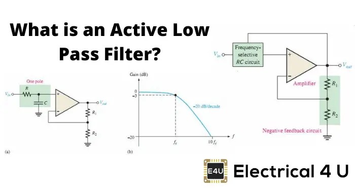
Signal processingScience news and electronic circuits: band pass filter circuit Filter pass low active signal processing electrical4uActive band pass filter circuit diagram and its frequency response.
Filter pass circuitBand pass filter: circuit diagram, types, calculator and its applications Questions about active band pass filterSchematic variable amplifier.

Active Band Pass Filter Circuit Diagram and Its Frequency Response

whats the difference between a cascaded band pass filter and a normal

ac - How does a RC Lowpass filter work? - Electrical Engineering Stack

Band Pass Filter: Circuit Diagram, Types, Calculator and Its Applications

Band Pass Filter Circuit Diagram

Questions about active band pass filter - Q&A - Operational Amplifiers

Band Pass Filter: What is it? (Circuit, Design & Transfer Function

Equivalent circuit for band pass filter | Download Scientific Diagram

Schematic diagram of 4th order Butterworth active Band-pass filter

Schematic diagram of the (a) band-pass filter, (b) variable gain